Một bản vẽ chế tạo chứa rất nhiều thông tin, nhưng QC chỉ cần đọc đúng một vài vùng, một vài quy ước, rồi có phương pháp để đối chiếu với cấu kiện thật.
Bố cục bản vẽ và bảng vật tư
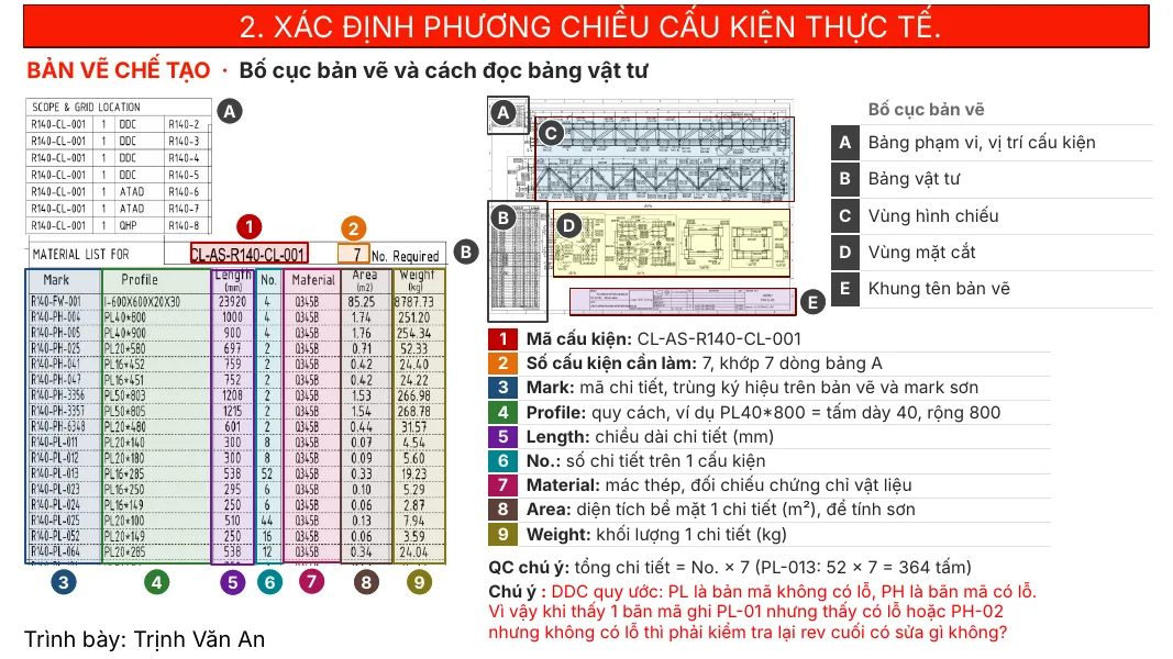
Bản vẽ gồm bảng phạm vi và vị trí cấu kiện, bảng vật tư, vùng hình chiếu, vùng mặt cắt và khung tên. Với bảng vật tư, đọc theo các cột:
- Mã cấu kiện và số cấu kiện cần làm (khớp số dòng trong bảng phạm vi).
- Mark: mã chi tiết, trùng ký hiệu trên bản vẽ và mark sơn.
- Profile: quy cách, ví dụ PL40*800 là tấm dày 40, rộng 800.
- Length: chiều dài chi tiết, đơn vị mm.
- No.: số chi tiết trên một cấu kiện.
- Material: mác thép, đối chiếu chứng chỉ vật liệu.
- Area: diện tích bề mặt một chi tiết (m²), dùng để tính sơn.
- Weight: khối lượng một chi tiết (kg).
QC cần chú ý hai điểm. Thứ nhất, tổng số chi tiết bằng No. nhân với số cấu kiện, ví dụ 52 nhân 7 bằng 364 tấm. Thứ hai, quy ước nội bộ của nhà máy: PL là bản mã không có lỗ, PH là bản mã có lỗ. Nếu bản mã ghi PL nhưng có lỗ, hoặc ghi PH mà không có lỗ, hãy kiểm tra lại revision cuối cùng xem có chỉnh sửa gì không.
Đọc các loại nét
- Nét liền: chi tiết nhìn thấy. Nét đứt: chi tiết bị che khuất. Nét đứt đường tâm: đường chia tâm, không phải chi tiết.
- Tên bản mã trong khung nét đứt: chi tiết bị che khuất; trong khung nét liền: chi tiết nhìn thấy. Mũi tên chỉ vị trí thực tế.
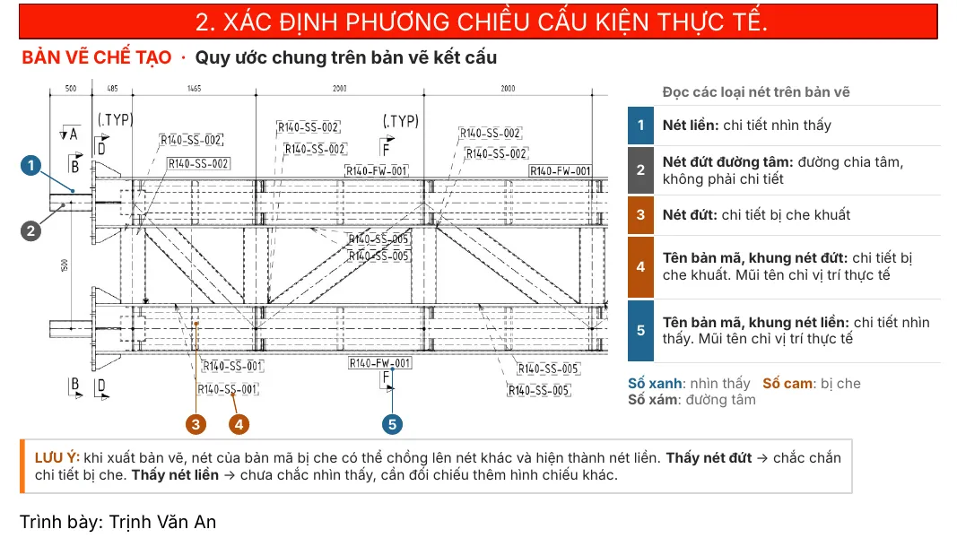
Lưu ý: khi xuất bản vẽ, nét của bản mã bị che có thể chồng lên nét khác và hiện thành nét liền. Thấy nét đứt thì chắc chắn chi tiết bị che; thấy nét liền thì chưa chắc nhìn thấy, cần đối chiếu thêm hình chiếu khác.
Vị trí đặc biệt 1: hệ lỗ bản mã không đối xứng
Hệ lỗ trên bản mã thường cách đều, đối xứng và song song với cạnh bản mã. Khi không như vậy, hãy đối chiếu lại bản vẽ hoặc mô hình 3D. Ba dấu hiệu hay gặp: đường nối tâm các lỗ không song song với cạnh; khoảng cách giữa hai hàng lỗ nhỏ bất thường và không đối xứng qua tâm; khoảng cách từ hai hàng lỗ ngoài cùng đến mép không đều nhau.
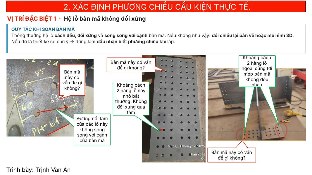
Nếu đó là thiết kế có chủ ý, hãy xem nó là dấu nhận biết phương chiều khi lắp.
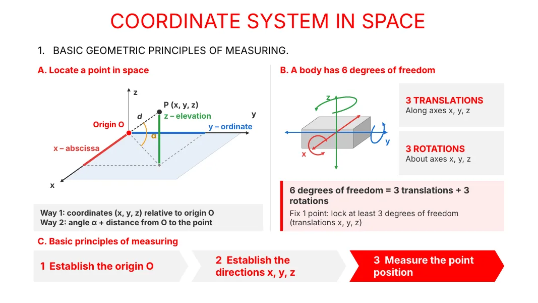
Hệ tọa độ khi đo
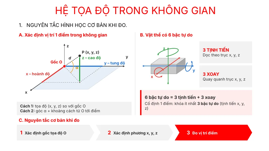
Vị trí một điểm trong không gian được xác định bằng tọa độ (x, y, z) so với gốc O, hoặc bằng một góc và một khoảng cách từ O. Một vật thể có 6 bậc tự do: 3 tịnh tiến dọc các trục và 3 xoay quanh các trục. Muốn cố định một điểm cần khóa ít nhất 3 bậc tịnh tiến. Từ đó có ba bước khi đo: xác định gốc tọa độ O, xác định phương x, y, z, rồi đo vị trí điểm.
Quy tắc bàn tay trái
Đối chiếu bản vẽ với cấu kiện thật là bước dễ nhầm nhất, nhất là khi cấu kiện nằm trên giá còn bản vẽ nhìn từ phía khác. Quy tắc bàn tay trái biến việc đó thành một động tác cụ thể.
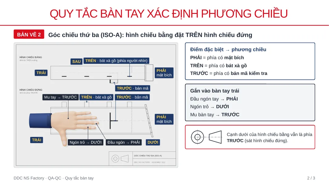
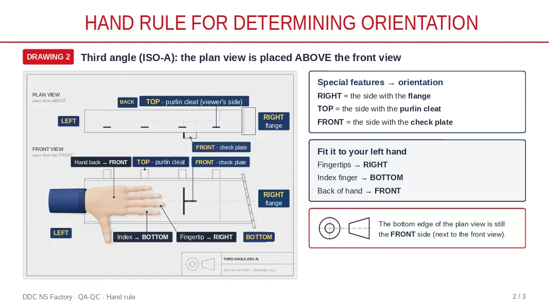
Trước hết chọn các điểm đặc biệt làm chuẩn, ví dụ PHẢI là phía có mặt bích, TRÊN là phía có bát xà gồ, TRƯỚC là phía có bản mã kiểm tra. Sau đó gắn vào bàn tay trái: đầu ngón tay chỉ PHẢI, ngón trỏ chỉ DƯỚI, mu bàn tay hướng TRƯỚC.
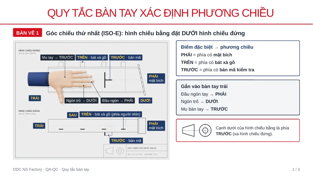
Quy tắc này dùng được cho cả hai góc chiếu, vì ở cả hai góc, cạnh dưới của hình chiếu bằng đều là phía trước.
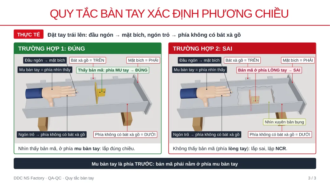
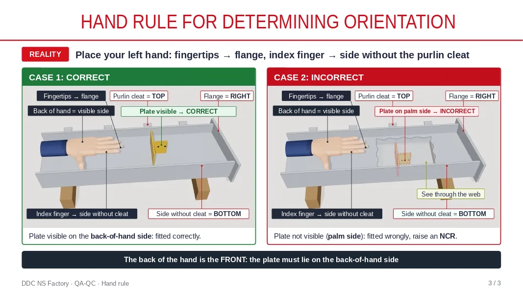
Áp dụng lên cấu kiện thật: đặt tay trái lên, đầu ngón về phía mặt bích, ngón trỏ về phía không có bát xà gồ. Nhìn thấy bản mã ở phía mu bàn tay thì lắp đúng chiều; không thấy bản mã (nó nằm phía lòng bàn tay) thì lắp sai, lập NCR.
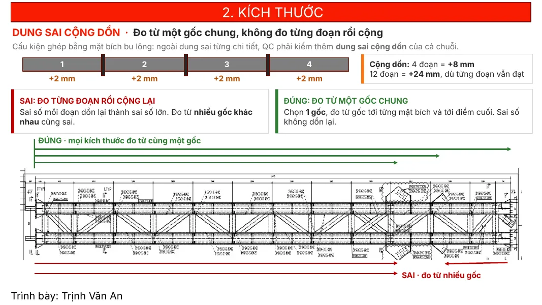
Dung sai cộng dồn
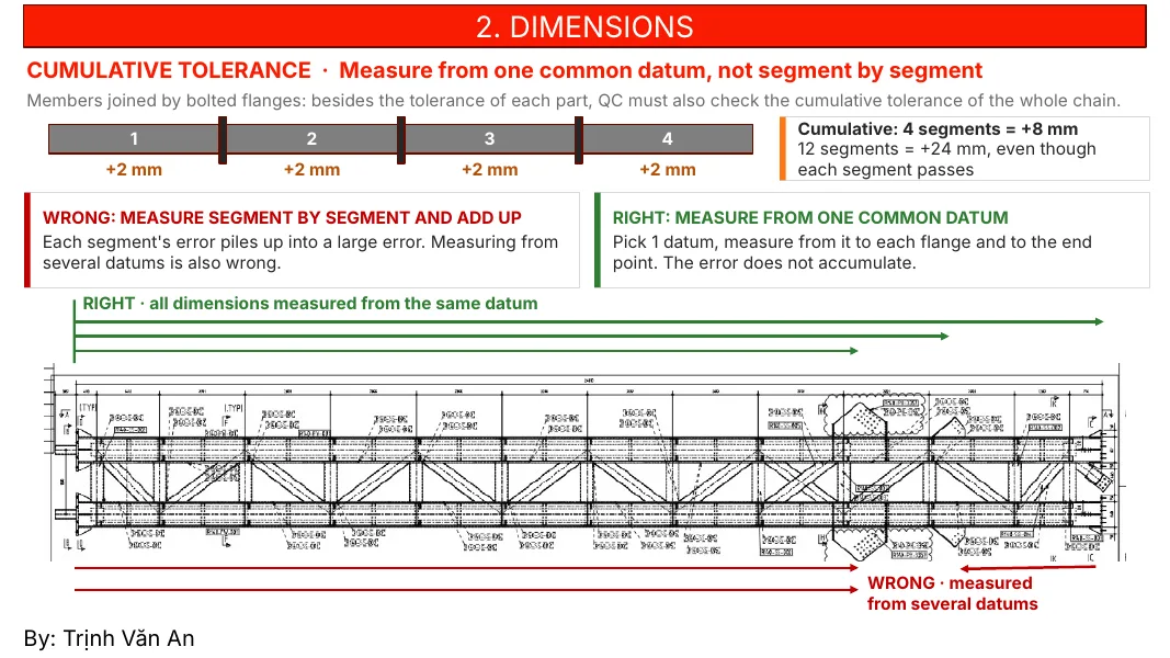
Với cấu kiện ghép bằng mặt bích bu lông, ngoài dung sai từng chi tiết, QC phải kiểm thêm dung sai cộng dồn của cả chuỗi. Giả sử mỗi đoạn lệch +2 mm: bốn đoạn cộng dồn thành +8 mm, mười hai đoạn thành +24 mm, dù từng đoạn vẫn đạt.
- Sai: đo từng đoạn rồi cộng lại, hoặc đo từ nhiều gốc khác nhau.
- Đúng: chọn một gốc chung, đo từ gốc tới từng mặt bích và tới điểm cuối. Sai số không dồn lại.
A fabrication drawing holds a great deal of information, but QC only needs to read a few areas and a few conventions correctly, and then have a method to compare it with the real member.
Drawing layout and the material list
The drawing has a scope and member-position table, a material list, a view area, a section area and a title block. Read the material list column by column:
- Member code and the number of members to make (matching the rows of the scope table).
- Mark: the part code, identical to the mark on the drawing and the paint mark.
- Profile: the size, for example PL40*800 is a plate 40 thick and 800 wide.
- Length: part length in mm.
- No.: number of parts per member.
- Material: steel grade, checked against the material certificate.
- Area: surface area of one part (m²), used for painting quantities.
- Weight: mass of one part (kg).
Two points for QC. First, the total number of parts is No. multiplied by the number of members: 52 × 7 = 364 plates. Second, the plant's internal convention: PL is a plate without holes and PH is a plate with holes. If a plate is marked PL but has holes, or marked PH but has none, check the latest revision for changes.
Reading line types
- Solid line: visible part. Dashed line: hidden part. Dashed centre line: a centring line, not a part.
- A plate name in a dashed box is a hidden part; in a solid box it is visible. The arrow shows the actual position.
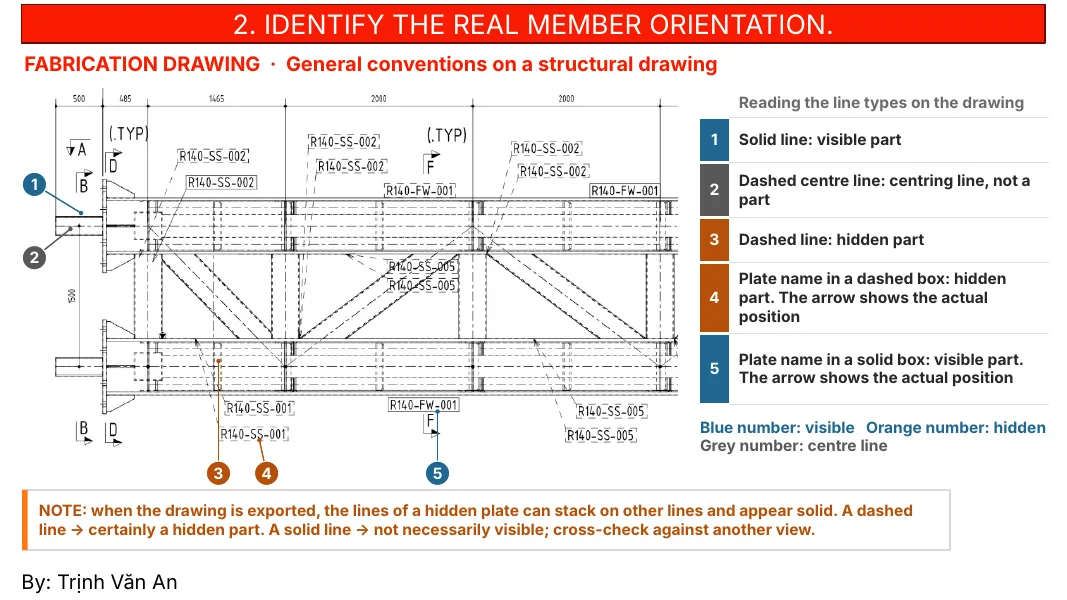
Note: when the drawing is exported, the lines of a hidden plate can stack on other lines and appear solid. A dashed line is certainly a hidden part; a solid line is not necessarily visible, so cross-check against another view.
Special position 1: an asymmetric hole pattern
Holes on a plate are normally evenly spaced, symmetric and parallel to the plate edges. When they are not, check the drawing or the 3D model again. Three common signs: the line through the hole centres is not parallel to the edge; the spacing between two rows is unusually small and not symmetric about the centre; the distances from the two outer rows to the plate edge are unequal.
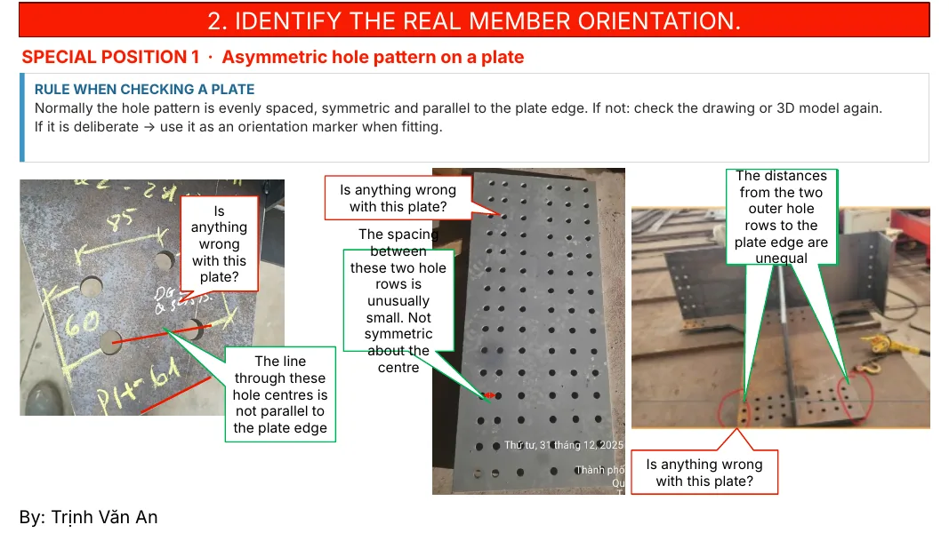
If it is deliberate, treat it as an orientation marker during fit-up.
The coordinate system for measuring
The position of a point is defined by coordinates (x, y, z) relative to an origin O, or by an angle and a distance from O. A body has 6 degrees of freedom: 3 translations along the axes and 3 rotations about them. To fix a point you must lock at least the 3 translations. This gives three steps for measuring: establish the origin O, establish the x, y, z directions, then measure the point.
The left-hand rule
Matching a drawing to the real member is the easiest step to get wrong, especially when the member lies on a rack and the drawing is seen from another side. The left-hand rule turns it into a physical gesture.
First pick distinctive features as references, for example RIGHT is the side with the flange, TOP is the side with the purlin cleat, FRONT is the side with the check plate. Then map them onto your left hand: fingertips point RIGHT, index finger points DOWN, back of the hand faces FRONT.
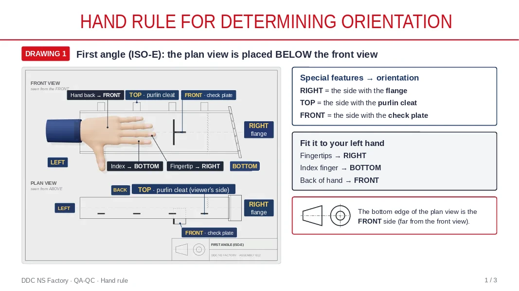
The rule works for both projection systems, because in both the bottom edge of the plan view is the front.
On the real member: place your left hand with fingertips toward the flange and the index finger toward the side without the purlin cleat. If you see the plate on the back-of-hand side, the member is fitted correctly; if you cannot see it (it is on the palm side), it is fitted wrongly and an NCR is raised.
Cumulative tolerance
For members joined by bolted flanges, besides the tolerance on each part QC must also check the cumulative tolerance of the whole chain. If every segment is +2 mm, four segments accumulate to +8 mm and twelve to +24 mm, even though each one passes.
- Wrong: measuring segment by segment and adding up, or measuring from several datums.
- Right: pick one common datum and measure from it to each flange and to the end point. The error does not accumulate.